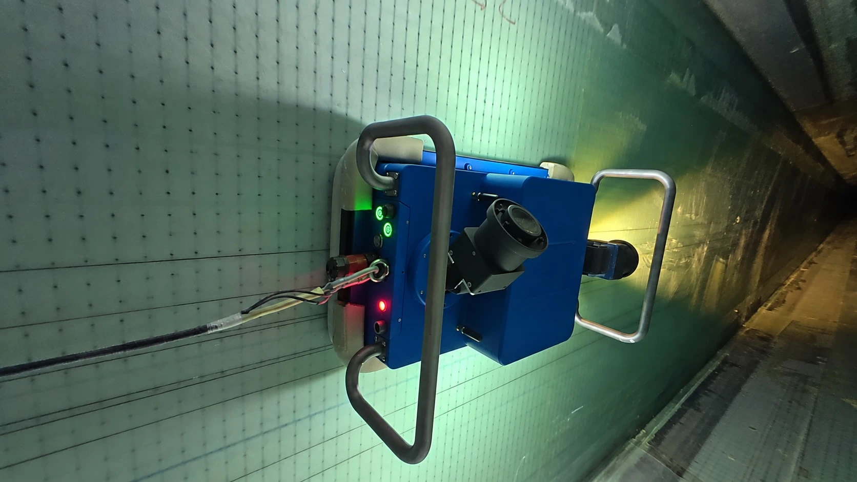
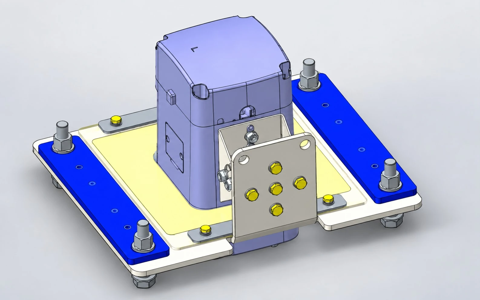
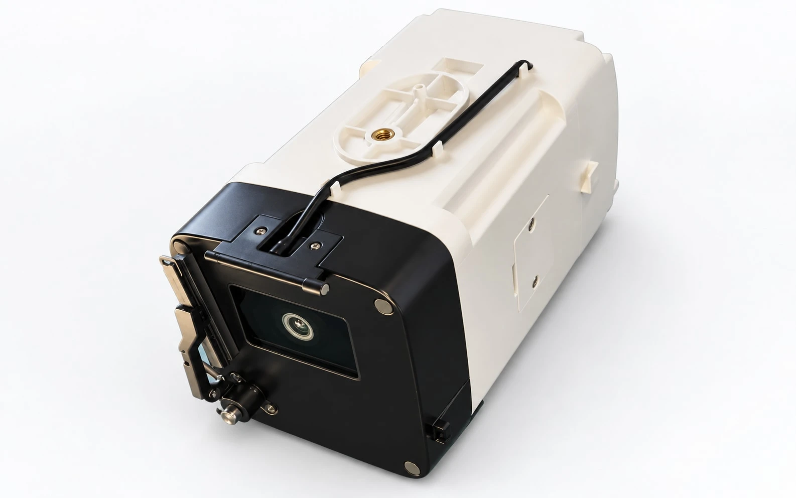
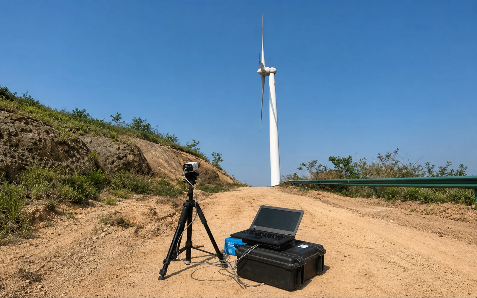
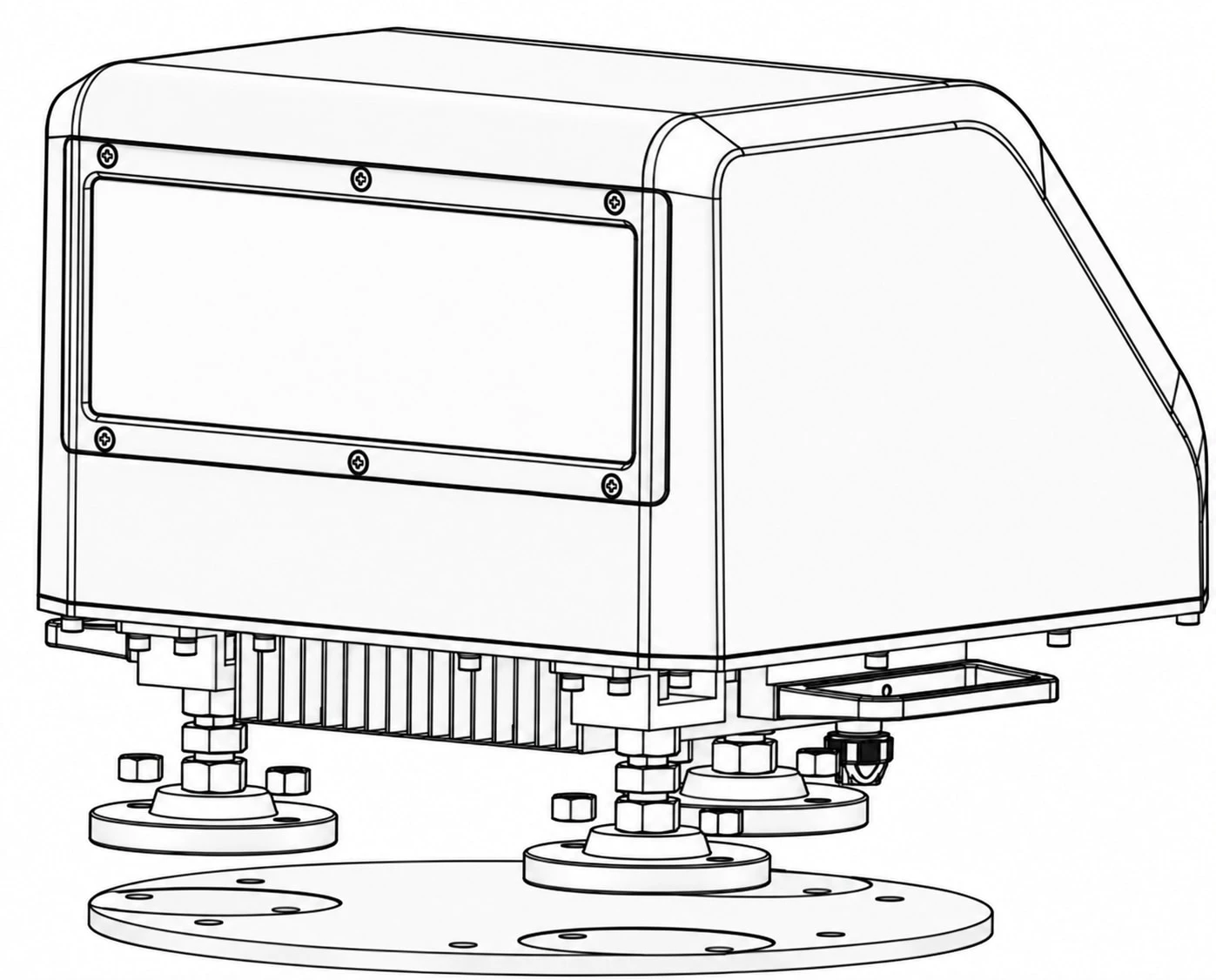
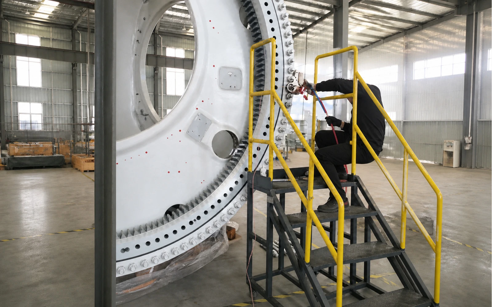
Every published number remains paired with its measurement meaning and source condition. Asterisked values require the configuration notes on the product page. Product cards use the supplied field imagery, equipment views, engineering renders and drawings identified on each card.
01
Blade Inspection & Clearance
Capture blade-interior evidence or measure blade-to-tower clearance with the sensing method matched to the site condition.
WIT-BR60
Wind Turbine Blade Inspection Robot
A negative-pressure crawler with multiple cameras, remote control and AI-assisted defect review for visual inspection inside wind-turbine blades.
Forward-looking wind measurement across multiple distance layers, with wind-speed and direction data available for monitoring and project-specific turbine control inputs.
Multiple illuminated camera views record accessible blade-interior surfaces.
Selected findings are organized into a structured report for human review.
The 70 m / ≤60 min value applies to one cavity over a 70 m internal area in a 95 m blade, with the stated setup and an unobstructed robot path. The 70% coverage statement is a separate product-document value.
No interface is specified in this published summary; confirm for the selected configuration.
Nacelle-mounted imaging records blade passage with documented night illumination.
Historical video and structured data support retrieval and project integration.
Accuracy and enclosure values are product-document specifications. Turbine actions depend on project integration, calibration, data quality and controller logic; predictive functions require controller data.
Industrial-bus output for project-specific controller logic
An 80 GHz FMCW radar measures range while a camera records visual context.
Video and point-cloud event records can be stored for later review.
Range and accuracy are product-document specifications. The source excludes extreme conditions involving dense fog together with rain or snow. Output-rate wording remains held from publication pending reconciliation; only the documented acquisition rate is shown.
Supported industrial interfaces include Modbus and CANopen
A positioned ground camera records the turbine under documented capture conditions.
Calculated results can be exported in a Word report for engineering review.
Performance depends on camera position, turbine yaw, image stability, visibility and the documented capture conditions. Drone configuration is optional and project-specific.
No interface is specified in this published summary; confirm for the selected configuration.
Doppler sensing collects forward wind speed and direction across configured range layers.
Second- and minute-level data are available through supported project interfaces.
Values are product-document specifications. Control outcomes depend on installation, project integration, turbine controller logic and operating conditions.
Ultrasonic feedback measures bolt axial force using the calibrated bolt parameters.
The system stops within the configured tolerance and stores analysis and process data.
Accuracy depends on the documented calibration workflow, bolt parameters, sensor coupling, selected tooling and operating procedure. The axial-force coefficient is normally established by calibration.
No interface is specified in this published summary; confirm for the selected configuration.
Selected findings are organized into a structured report for human review.
Measurement, conditions & interfaces
Sensing / measurement
Multiple illuminated camera views record accessible blade-interior surfaces.
Operating conditions
The 70 m / ≤60 min value applies to one cavity over a 70 m internal area in a 95 m blade, with the stated setup and an unobstructed robot path. The 70% coverage statement is a separate product-document value.
Interfaces
No interface is specified in this published summary; confirm for the selected configuration.
Historical video and structured data support retrieval and project integration.
Measurement, conditions & interfaces
Sensing / measurement
Nacelle-mounted imaging records blade passage with documented night illumination.
Operating conditions
Accuracy and enclosure values are product-document specifications. Turbine actions depend on project integration, calibration, data quality and controller logic; predictive functions require controller data.
Interfaces
Industrial-bus output for project-specific controller logic
Video and point-cloud event records can be stored for later review.
Measurement, conditions & interfaces
Sensing / measurement
An 80 GHz FMCW radar measures range while a camera records visual context.
Operating conditions
Range and accuracy are product-document specifications. The source excludes extreme conditions involving dense fog together with rain or snow. Output-rate wording remains held from publication pending reconciliation; only the documented acquisition rate is shown.
Interfaces
Supported industrial interfaces include Modbus and CANopen
Calculated results can be exported in a Word report for engineering review.
Measurement, conditions & interfaces
Sensing / measurement
A positioned ground camera records the turbine under documented capture conditions.
Operating conditions
Performance depends on camera position, turbine yaw, image stability, visibility and the documented capture conditions. Drone configuration is optional and project-specific.
Interfaces
No interface is specified in this published summary; confirm for the selected configuration.
Second- and minute-level data are available through supported project interfaces.
Measurement, conditions & interfaces
Sensing / measurement
Doppler sensing collects forward wind speed and direction across configured range layers.
Operating conditions
Values are product-document specifications. Control outcomes depend on installation, project integration, turbine controller logic and operating conditions.
The system stops within the configured tolerance and stores analysis and process data.
Measurement, conditions & interfaces
Sensing / measurement
Ultrasonic feedback measures bolt axial force using the calibrated bolt parameters.
Operating conditions
Accuracy depends on the documented calibration workflow, bolt parameters, sensor coupling, selected tooling and operating procedure. The axial-force coefficient is normally established by calibration.
Interfaces
No interface is specified in this published summary; confirm for the selected configuration.
Configuration before comparison
Share the component and required output.
We will map the requirement to a documented system and identify the inputs needed for a technical review.