Application finder

Choose by inspection task.

Select the task, then verify the component, environment, output and operating conditions against a documented system.

Locate the inspection question

One turbine. Different evidence zones.

Use the numbered zones to connect your task to the six documented systems.

Conceptual wind-turbine inspection zonesZone 1 is inside a blade. Zone 2 represents video or radar-camera blade-clearance sensing near the nacelle. Zone 3 is ground-based rotor observation. Zone 4 is nacelle forward-wind measurement. Zone 5 is a separate joint symbol: the actual joint location varies. The six-model HTML legend provides the details. This is not an installation drawing.0102030405Joint location varies
Conceptual schematic. Not to scale or an installation plan. Marker positions do not specify mounting points, dimensions or clearances.
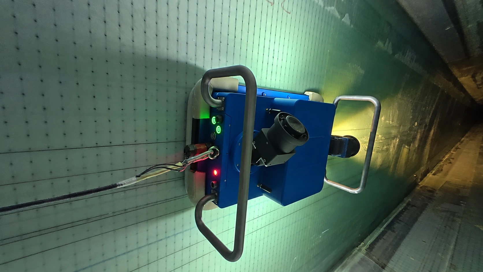
  1. Zone 01: Inside an accessible blade cavity

    WIT-BR60

    Internal imagery, location recording and human-reviewed reporting. Entry, traversable path and recovery need review.

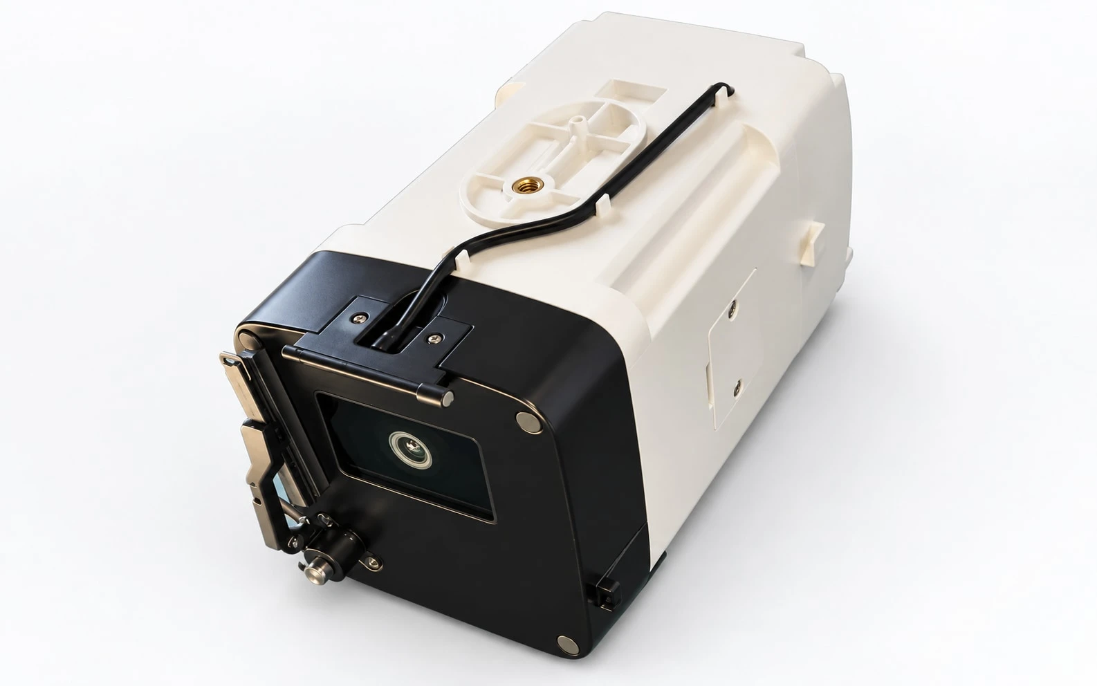
  2. Zone 02: Nacelle-based video clearance

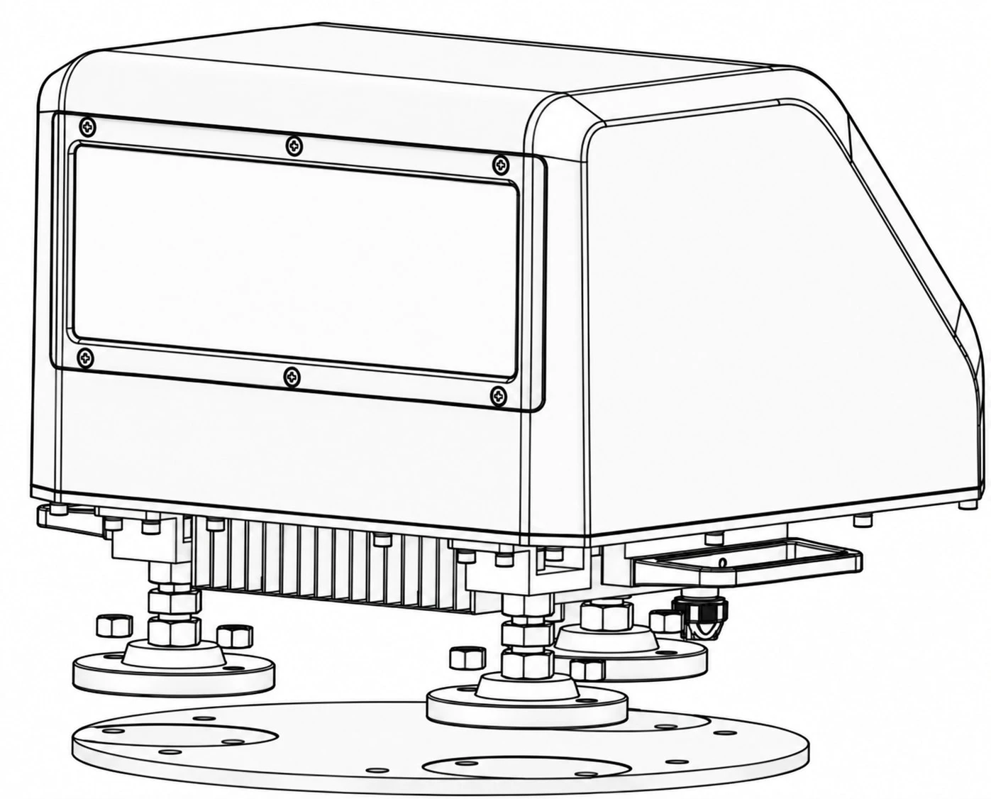
    WIT-VC20

    Video of blade passage supports clearance calculation and retained records. Mounting, lighting and controller integration are project-specific.

  3. Zone 02: Radar–camera clearance

    WIT-RC30

    Radar ranging and camera context support clearance-event records. Review installation geometry and documented environmental exclusions.

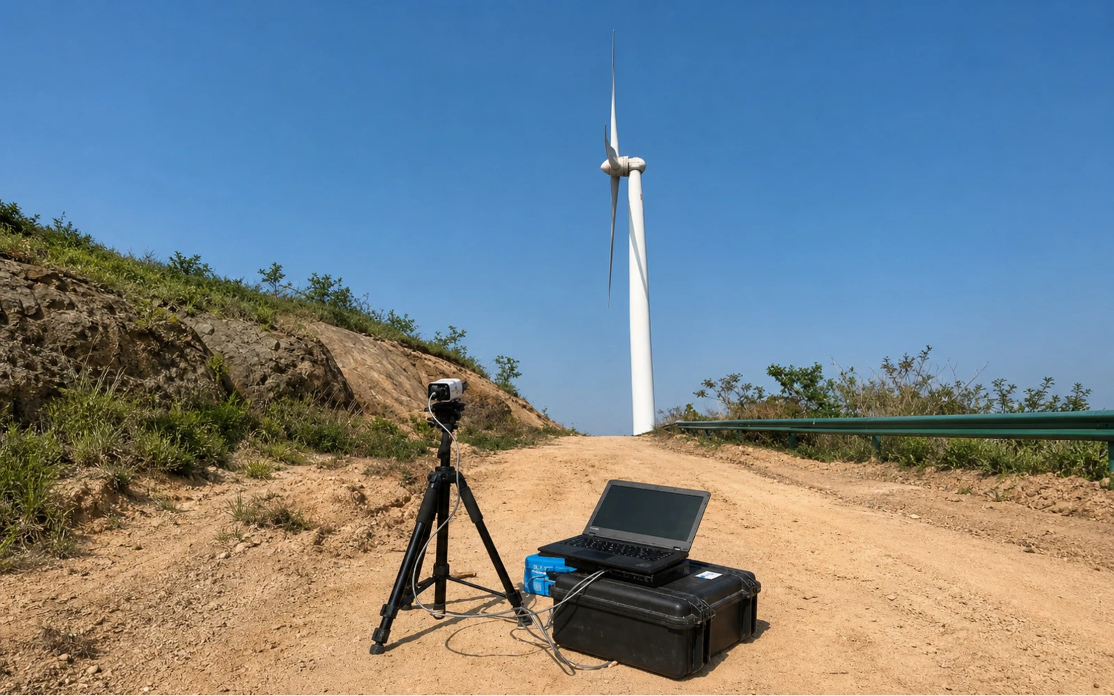
  4. Zone 03: Ground-based rotor observation

    WIT-RB20

    A positioned camera captures turbine video for rotor comparison and report output. Camera position, visibility and image stability matter.

  5. Zone 04: Forward wind from the nacelle

    WIT-WL40

    Lidar measures forward wind across configured distance layers. Installation and controller use require a project review.

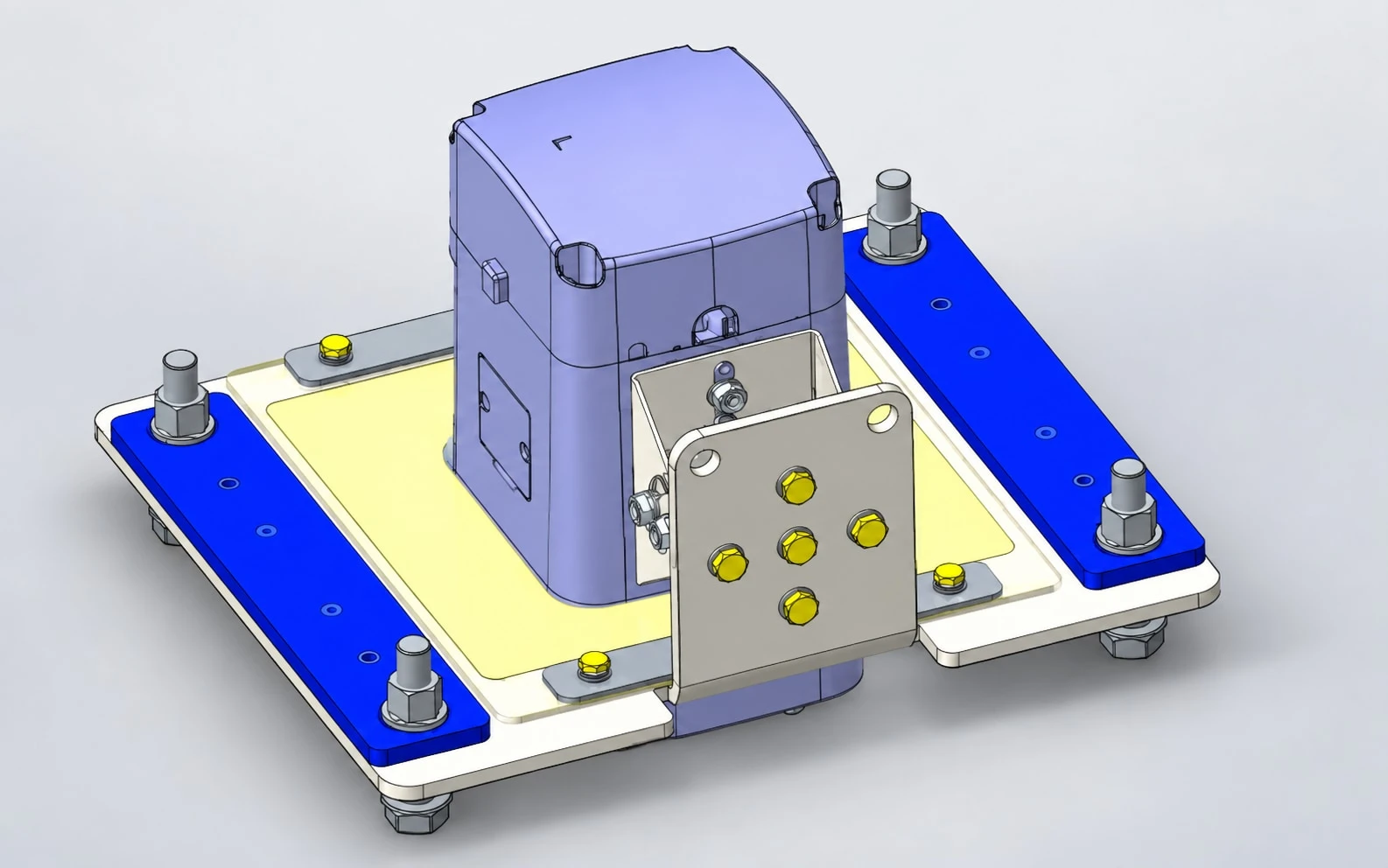
  6. Zone 05: The joint being tightened

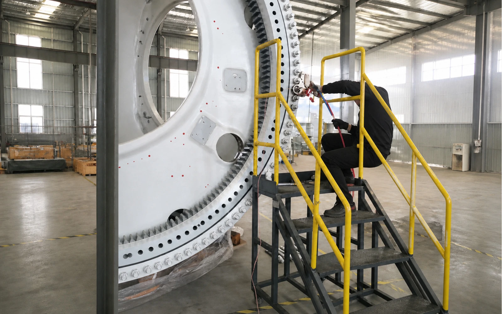
    WIT-BW10

    Ultrasonic axial-force feedback supports controlled tightening and process records. Joint location varies; tooling, access and calibration determine fit.

Five starting points

Match task, evidence and inputs.

The product links below are starting points, not automatic recommendations. Final suitability depends on the documented conditions and project configuration.

01

See and document the blade interior

Use when the decision depends on internal visual evidence, defect location records and a structured review workflow.

Prepare for review

Blade type and length, cavity access, expected obstructions, required coverage and report format.

Usually written against IEC 61400-5:2020 — rotor blades for wind turbines, including provisions for in-service inspection. Naming the standard is a reference, not a claim of conformity.

Discuss this task

02

Measure blade-to-tower clearance

Choose video or radar–camera sensing according to range, visibility, retained evidence and controller-integration requirements.

Prepare for review

Turbine geometry, mounting position, environmental range, controller interface and required event history.

Usually written against IEC 61400-1:2019 — design requirements for structural integrity, which is where a blade-to-tower clearance requirement originates. Naming the standard is a reference, not a claim of conformity.

Discuss this task

03

Review rotor imbalance offline

Use a field capture when the task is to compare rotor behaviour, clearance variation and aerodynamic imbalance without permanent installation.

Prepare for review

Turbine dimensions, safe observation position, expected weather window and available capture duration.

Usually written against ISO 20816-21:2025 — measurement and evaluation of machine vibration for wind turbines. Naming the standard is a reference, not a claim of conformity.

Discuss this task

04

Measure forward wind at the nacelle

Use when forward wind speed and direction data are required for monitoring or project-specific control inputs.

Prepare for review

Measurement layers, installation geometry, data interface, controller logic scope and operating envelope.

Usually written against IEC 61400-50-3:2022 — use of nacelle-mounted lidar for wind measurement. Naming the standard is a reference, not a claim of conformity.

Discuss this task

05

Control and record bolt preload

Use ultrasonic feedback when tightening must be assessed against a configured axial-force target and the process record retained.

Prepare for review

Bolt size and material, joint design, target preload, calibration method, tooling access and acceptance tolerance.

Usually written against ISO 16047:2005 — torque/clamp-force testing of threaded fasteners, which requires the relationship to be established by test rather than assumed. Naming the standard is a reference, not a claim of conformity.

Discuss this task Or have the load verification done as an engagement

A useful first review

Bring the constraint, not only the model.

Clear configuration inputs help separate a documented specification from a project-specific outcome.

  • 01Component

    Geometry, material, access and known exclusions.

  • 02Environment

    Weather, visibility, temperature and installation conditions.

  • 03Output

    Images, measurements, records, reports or controller data.

  • 04Decision

    The maintenance, engineering or procurement decision the evidence must support.

Application review

Not sure which sensing method fits the site?

Describe the component, operating envelope and required output. We will identify the documented configuration questions to resolve.

Technical enquiry

sales@WindInspectTech.comWhatsApp sales
At least 20 characters. Do not include passwords, credentials, export-controlled files or confidential design data.
Company and destination (optional)
Useful technical inputs (optional)

Component, operating condition, required output and preferred data interface.

Inquiry route
Use email insteadBy submitting, you confirm that you have read the Privacy Notice. Product values remain configuration-specific and require application review.